- Height of upper arm is adjusted by turning screw in either direction (refer to plan image above)
- Shoulder hook is lined with dense neoprene, 3/16Ó thick sponge rubber tape. Use Ó wide in 2 strips to line the 1 Ó wide aluminum.
- When purchasing steel tubing, be sure 5/8Ó sq. slides into Ó sq. without binding.
- Use -20 Allen head cap screws with nylon lock nuts at swivel joints, lower arm adjustment, and camcorder platform slide.
- Camcorder slide parts are all made from the same 1 ÓX1 Ó aluminum angle, by cutting angle legs to the sizes indicated.
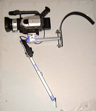
- In use, bracket at bottom end of the brace, is hooked behind a leather belt. Bracket can be made larger, lined with Velcro, and with Velcro on a belt, used to support the brace.
- In forming the radius of the shoulder hook, I cut a radius out of Ó plywood, and used it to bend the aluminum to shape. ItÕs advisable to make a paper template to check while youÕre bending.
- When drilling and tapping the hole in the upper arm, make certain that the end of the upper arm will be snug against the aluminum surface, to insure that the connection will be rigid, even if it means drilling the hole slightly further from the end, and filing to fit.
- I chose to use a Bogen quick-release device on the camcorder platform, because it matched the one on my tripod, but cost more than all the rest of the parts combined.
- If I forgot anything, e-mail me at dcdziner@pacbell.net

[ Learning Centre ] [ Troubleshooting ] [ Downloads ] [ Gallery ] [ Wishlist ] [ Links ] [ Email ]
© 2001, No One In Particular, Inc. This site is not affiliated with Autodesk Discreet .
Stealing from this site is prohibited unless you ask nicely.